

close
Choose Your Site
Global
Social Media

Author: Site Editor Publish Time: 2026-07-07 Origin: Site
For fenestration fabricators and OEM designers, upgrading thermal performance is no longer just about adding a basic barrier. It requires exact geometric precision to succeed. Modern architectural demands constantly push aluminum window systems to their absolute physical limits. Specifying a thermal break polyamide strip based solely on generic thermal conductivity values often creates significant engineering problems. This narrow focus routinely leads to catastrophic structural failure, severe assembly line bowing, or unexpected hardware interference during fabrication.
Optimal window and facade engineering demands a delicate, calculated balance. You must carefully weigh ambitious Uf-value targets against necessary shear strength requirements. This critical equilibrium is dictated entirely by the strip’s overall width, internal profile shape, and core material integrity. We will explore how these specific geometric and material choices shape structural outcomes. By mastering these variables, you can eliminate scrap waste, streamline your assembly machinery, and engineer highly resilient, energy-efficient aluminum window systems.
Width Dictates the Trade-Off: Increasing strip width exponentially improves thermal insulation but proportionally reduces the composite assembly's structural rigidity unless shape geometry compensates.
Shape Drives Assembly Success: I-shapes, C-shapes, and hollow multi-cavity designs directly dictate rolling machinery setup, knurling grip, and hardware compatibility.
Material Non-Negotiables: Complex profile shapes rely on the tensile strength and thermal stability of PA66GF25 insulating strips to survive 200°C+ powder-coating processes without distorting.
Hidden Costs: Incorrect shape specifications lead to high scrap rates during aluminum extrusion assembly due to asymmetric shear forces.
Creating a wide barrier blocks heat effectively. The fundamental physics of thermal bridging rely entirely on this principle. Conduction requires a continuous physical path to transfer thermal energy. Aluminum possesses a very high thermal conductivity rate. A wider gap between interior and exterior aluminum extrusions disrupts this conductive path. This disruption serves as the most direct route to lowering thermal transmittance. Lower Uf-values always require wider separation between the metal halves.
However, you cannot infinitely expand this gap. Wider strips introduce severe structural vulnerabilities. They act as the primary load-bearing bridge between two rigid aluminum halves. When you increase the width, the bending moment increases proportionally. Heavy insulated glazing units place immense dead weight directly on the sill. High-rise buildings subject the facade to aggressive, sustained wind loads. Overly wide, unreinforced profiles will deflect under this pressure. This deflection compromises weather seals and causes expensive glass units to fail.
You must evaluate load-bearing requirements against localized energy codes. Sometimes, architectural demands prioritize slim sightlines over aggressive passive-house U-values. In these specific cases, you should specify narrow thermal break profiles. They provide an ideal solution for internal partition walls. They also excel in warm-climate commercial facades. Space-constrained architectural systems benefit greatly from their compact dimensions. Narrow profiles maintain exceptional shear strength. They keep the aluminum halves tightly bound against lateral forces. You sacrifice some thermal resistance but gain immense structural reliability.
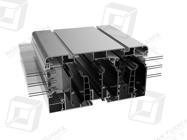
Choosing the right cross-sectional shape directly influences assembly success. We must match the profile geometry to the specific window system design. Each shape serves a distinct structural and functional purpose.
The I-shape profile provides straightforward lateral bridging. Its mechanism relies on a simple, robust rectangular cross-section. These solid profiles transfer shear loads linearly across the thermal gap. They offer highly predictable shear strength under pressure. We recommend them heavily for standard commercial windows. They support rapid, high-yield assembly processes on the factory floor. Factory operators can easily calibrate knurling wheels to lock them in place. The minimal complexity ensures very low scrap rates during production.
C-shape profiles feature a distinct curved or angled geometry. Their mechanism intentionally creates interior space within the window frame. This extra space easily accommodates standard Euro-groove hardware. It also allows necessary clearance for complex multi-point locking mechanisms. You can even design specific water drainage paths through the curvature.
However, you must exercise caution during evaluation. Complex operable windows absolutely require C-shapes. But they demand precise cavity alignment during the knurling process. If the rolling machine applies uneven pressure, the curved profile may tilt. This tilt ruins the final extrusion alignment and renders the frame unusable.
Advanced architectural systems often demand extreme thermal efficiency. Hollow profiles introduce trapped air pockets between the aluminum halves. Some premium variants even feature integrated foam fins. These internal cavities effectively disrupt convection currents inside the frame.
We highly recommend multi-cavity designs for Passive House standard systems. They maximize thermal resistance without expanding the overall frame width excessively. Despite their impressive benefits, they carry specific manufacturing risks. You need advanced extrusion precision to produce them correctly. Wall thickness variations pose a significant threat. Uneven cavity walls can lead to fatal crushing during the rolling process. Operators must calibrate crimping pressure perfectly to avoid collapsing the hollow chambers.
Profile Geometry | Primary Mechanism | Best Application | Manufacturing Risk Level |
|---|---|---|---|
I-Shape | Straightforward lateral bridging. | Standard commercial windows, fast assembly lines. | Low. Predictable shear strength and easy rolling setup. |
C-Shape | Creates clearance for hardware and drainage. | Operable windows requiring Euro-groove hardware. | Medium. Requires precise cavity alignment during knurling. |
Hollow / Multi-Cavity | Traps air to disrupt thermal convection currents. | Passive House standard systems. | High. Prone to crushing if rolling pressure is excessive. |
When specifying intricate geometric shapes, material composition becomes absolutely critical. We use Polyamide 66 reinforced with 25% glass fiber as the baseline standard. Standard plastics simply cannot handle the mechanical stress of window fabrication. PA66GF25 insulating strips deliver unparalleled mechanical properties. This specific composite blend defines modern, high-performance fenestration engineering.
Dimensional stability separates successful assemblies from costly factory failures. Microscopic glass fibers inside the polyamide matrix align parallel to the extrusion direction. This uniform alignment provides immense tensile strength. Complex C-shapes and thin-walled hollow chambers rely heavily on this internal reinforcement. They must maintain their exact structural integrity during extreme temperature cycles.
Aluminum profiles undergo powder coating and anodizing after the thermal barrier assembly. These high-temperature baking processes routinely exceed 200°C. Standard thermoplastics would melt, warp, or severely distort. PA66GF25 survives these harsh environments flawlessly. It holds the aluminum extrusions in perfect alignment throughout the entire oven curing cycle.
You might wonder about alternative thermal barrier methods. Let us compare polyamide extrusion to traditional polyurethane pour-and-debridge systems. Poured polyurethane involves injecting liquid resin directly into a prepared aluminum channel. You then physically cut away the temporary aluminum bridge at the bottom. This method creates a basic, continuous thermal block.
However, poured polyurethane cannot replicate complex structural geometries. It cannot form hollow air chambers to boost U-values. It cannot create curved cavities to accommodate locking hardware. Extruded polyamide struts achieve these hardware-accommodating geometries effortlessly.
Furthermore, objective testing reveals stark differences in thermal flex capabilities. Polyamide expands and contracts at a rate nearly identical to aluminum. Polyurethane exhibits vastly different thermal expansion coefficients. Extreme temperature fluctuations cause polyurethane systems to stress and shear over time. Polyamide struts absorb this daily thermal stress predictably without degrading the mechanical bond.
Selecting an incorrect shape or material triggers a cascade of production issues. These implementation risks severely disrupt factory operations and delay project timelines. We must understand these failure modes to prevent them proactively.
Mismatched strip shapes and aluminum cavities create severe alignment issues. Asymmetric geometries require precisely calibrated, custom rolling wheels. If the machinery applies uniform pressure to an uneven shape, disaster strikes immediately. The uneven pressure distribution causes the final window profile to bow. It may even twist dramatically on the assembly line.
A twisted profile cannot accommodate insulated glass units. It will not accept standard weather stripping. This alignment error generates massive amounts of scrap material. You lose both the expensive aluminum and the thermal barrier.
The strip "foot" serves as the critical interlocking edge. It must slide into the aluminum cavity perfectly. The knurling machine then crushes the aluminum hammer-head down tightly onto this foot. If you specify the wrong foot angle, the aluminum cannot bite properly.
The connection lacks sufficient friction and mechanical lock. This deficiency leads to catastrophic shear failure over time. The inner and outer aluminum frames may slide independently of one another. They might even separate entirely under extreme wind load stress. Always match the foot geometry to the specific extrusion die.
Complex profile corners experience massive stress during oven curing. The aluminum expands rapidly as it heats up in the powder-coating oven. The thermal barrier must flex to accommodate this sudden movement. If the polyamide blend lacks the necessary flexibility, it fails.
Inferior materials suffer from severe micro-cracking in the tight corners of C-shapes. These microscopic cracks compromise the entire structural integrity of the window. PA66GF25 prevents this specific failure mode. It matches the thermal expansion rate of the surrounding aluminum perfectly.
Procurement teams and extrusion engineers must collaborate closely during the design phase. Selecting the right geometric profile requires a systematic, evidence-based approach. Follow this logical sequence to ensure long-term production success.
Step 1: Define the Boundary Conditions. Start by mapping local U-value compliance mandates. You must balance these strict energy requirements against overall building height. Taller buildings dictate severe wind load conditions. This structural balance determines the maximum allowable strip width for your project. Do not exceed this width without adding structural reinforcements.
Step 2: Prototype Hardware Intersections. Never finalize a profile shape without checking hardware compatibility first. You must ensure the selected strip shape leaves adequate clearance. C-shapes often accommodate heavy-duty friction hinges much better than offset I-shapes. Multi-point locks require very specific cavity dimensions. Build physical or digital prototypes to verify these spatial relationships before ordering bulk materials.
Step 3: Conduct Die Validation. Theoretical dimensions often differ significantly from real-world aluminum extrusions. You should always request physical sample runs from the factory. Verify the strip's dimensional tolerances meticulously. They must stay within strict ±0.05mm limits. These dimensions must align exactly with the specific aluminum extrusion dies used in your facility. Worn extrusion dies will change the cavity size, so test frequently.
Selecting a thermal break component goes far beyond simply checking an energy-efficiency box. It represents a highly critical structural engineering decision. You must evaluate width and shape together as a holistic system. Maximizing width significantly improves thermal performance but inherently threatens structural rigidity. Choosing complex geometries solves difficult hardware challenges but simultaneously complicates the rolling process.
Consider these action-oriented next steps for your production facility:
Audit your current assembly line scrap rates immediately to identify recurring bowing or twisting issues.
Consult closely with extrusion engineers to match specific PA66GF25 profile shapes to your next-generation window designs.
Calibrate your factory rolling and knurling machinery carefully whenever you transition between I-shape and multi-cavity profiles.
Test prototype assemblies rigorously for sheer strength before committing to full-scale powder coating runs.
A: There is a strong linear correlation between the width of the polyamide barrier and the reduction of conductive heat transfer. A wider strip creates a larger physical gap between the interior and exterior aluminum profiles. This larger gap drastically reduces thermal bridging, directly lowering the window system's overall U-value.
A: Yes, narrow profiles can meet moderate energy codes when utilized intelligently. You can pair them with high-performance low-E glass and argon-filled insulated glazing units (IGUs) to compensate for the narrower barrier. However, strict passive house standards typically require wider, multi-cavity shapes to achieve ultimate thermal efficiency.
A: The glass fiber provides the essential tensile strength necessary for complex geometries. Without it, intricate shapes like C-curves and hollow chambers would snap easily under shear load. Additionally, the glass fiber prevents the plastic from melting, warping, or losing structural integrity during high-temperature powder coating processes.
A: Bowing usually results from mismatched dimensional tolerances between the strip shape and the aluminum cavity. It can also occur if the factory machinery applies uneven rolling pressure to asymmetrical strip geometries. Proper calibration of the knurling and rolling wheels is required to maintain perfectly straight profiles.


