

close
Choose Your Site
Global
Social Media

Author: Site Editor Publish Time: 2026-08-28 Origin: Site
The geometry of a thermal break plays a critical role in high-performance fenestration today. It acts as the structural and thermal backbone of energy-efficient modern building envelopes. Without precise alignment, these window and door systems fail to meet increasingly strict energy codes. Improper matching between a thermal strut and an aluminum extrusion cavity often causes catastrophic manufacturing issues. You will likely experience severe thermal bridging, compromised composite shear strength, and highly costly fabrication failures. The connection simply must perform flawlessly under stress. This guide gives engineers and fabricators a clear decision-stage framework to avoid these pitfalls. You will discover exactly how to evaluate cavity tolerances for optimal crimping bite. We will also explore the structural trade-offs required when balancing wind loads against aggressive insulation targets. Finally, you will learn how to validate your assembly using recognized industry testing standards to ensure long-term durability.
Tolerance alignment is non-negotiable: Even a 0.1mm variance in cavity design can cause rolling failures or profile slippage during the crimping process.
Form follows function: The choice between solid, hollow, C-shaped, or complex multi-cavity polyamide profiles must balance structural wind loads with target U-values.
Fabrication dictates design: Successful integration requires evaluating a supplier’s knurling and crimping data (DFM) before finalizing the extrusion die.
Standardized validation: Reliable matching must be verifiable against recognized industry standards (e.g., EN 14024 or AAMA TIR-A8) for composite shear strength.
Misalignment creates immediate financial risks for manufacturers. It also disrupts your overall production schedule significantly. When aluminum cavities do not perfectly match the strut geometry, you lose crucial shear strength. The crimping wheels cannot push the aluminum "hammers" deep enough into the plastic grooves. This loose fit prevents an adequate crimping bite. Under severe wind loads, structural delamination becomes a very real danger. The building envelope might fail entirely if the elements separate. A poorly matched Polyamide Profile cannot resist the expansion and contraction caused by daily temperature swings.
Fabricators suffer directly from these initial design flaws. They experience cracked profiles during the active rolling stage. Scrap rates skyrocket when components do not align smoothly. Production lines face unexpected downtime while operators attempt to adjust machine settings. This yields massive operational losses over time. You essentially throw away expensive raw materials and waste valuable labor hours.
Furthermore, you risk failing mandatory compliance tests. Thermal and structural certification tests demand uniform performance across the assembly. The composite structure must act as a single monolithic unit to pass. If the cavity allows microscopic movements, the assembly will definitely fail standard shear tests. Certification bodies will reject the fenestration system, blocking your market entry.
Watch out for these common fabrication failures caused by poor matching:
Micro-cracking along the strut edge due to uneven hammer pressure.
Longitudinal slippage during CNC machining and final cutting.
Water ingress through the thermal break joint during severe weather testing.
Bowing or twisting of the completed composite profile after cooling.
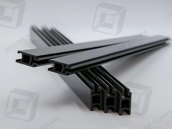
You must engineer the extrusion cavity strictly for mechanical integration. Dimensional tolerances require strict control at the extrusion die level. A variance of even 0.1mm ruins the intended fit. You need a precise "slide-in" tolerance before any crimping begins. If the cavity is too tight, manual insertion becomes impossible. Operators will struggle to feed the strut through the aluminum channel. If it is too loose, the final crimp lacks adequate holding strength.
Next, consider the hammer dimensions closely. These act as the retaining "teeth" of the aluminum profile. They must align perfectly with the designated grooves on your chosen strut. Mismatched angles prevent the aluminum from biting securely into the fiberglass-reinforced plastic. The angle of incidence determines how much aluminum material gets displaced into the strut groove. You want maximum displacement without shearing the plastic.
Alloy selection also matters immensely during assembly. Aluminum alloys like 6060 and 6063 behave differently under mechanical pressure. Their specific tempers dictate malleability during the critical crimping phase. A harder temper might crack or resist the heavy crimping wheels. A softer temper might bend too easily and fail to hold the strut securely under environmental stress. We recommend testing various tempers to find the ideal balance of yield strength and formability.
Finally, observe symmetry and proportions throughout the design. Follow clear Design for Manufacturability (DFM) rules diligently. Maintain a highly uniform wall thickness around the thermal cavity. This practice prevents thermal distortion during the initial extrusion process. Uneven walls cool at different rates, causing the cavity to warp before it even reaches the assembly line.
Follow these essential DFM steps for cavity design:
Define the precise insertion gap required for your specific strut width.
Calculate the exact angle of the aluminum retaining hammers.
Specify the alloy and temper to ensure consistent crimping malleability.
Balance the wall thickness around the cavity to prevent extrusion warping.
Draft a detailed tolerance map for both the aluminum and the plastic components.
Engineers constantly balance thermal performance against structural rigidity. Wider struts naturally improve insulation properties. They lower the overall U-value of the window system significantly. However, they inherently reduce the overall stiffness of the composite extrusion. You must evaluate this trade-off carefully. Choosing the right structural shape is crucial for a large Facade Polyamide Profile.
Profile shape selection dictates both assembly methods and final performance. Solid or I-shapes work best for standard structural stability. They offer straightforward cavity matching and resist compressive forces well. Hollow or multi-chamber shapes become necessary for stringent facade U-values. However, they require specialized cavity support blocks. Without these blocks, the hollow chambers often crush during the high-pressure assembly process. C-shapes and special geometries accommodate hardware integration or specialized thermal zoning. These require highly customized and often complex cavity designs.
You must also understand load transfer dynamics thoroughly. The matched cavity must distribute shear loads evenly across the entire joint. It also handles transversal loads generated by building sway or severe wind pressure. Poor cavity designs create intense stress concentrations. These localized stress points lead to long-term structural fatigue and eventual failure. The mechanical lock must remain rigid over decades of building movement.
Thermal Break Shape Comparison Chart
Profile Shape | Thermal Insulation Capability | Structural Rigidity | Cavity Matching Complexity |
|---|---|---|---|
Solid / I-Shape | Moderate | High | Straightforward |
Hollow / Multi-Chamber | Excellent | Moderate (Prone to crushing) | High (Requires internal support) |
C-Shape / Custom | Variable | Variable based on load direction | Very High |
You cannot guarantee performance without rigorous validation protocols. Knurling plays a foundational role in this mechanical joint. The cavity bed must undergo proper knurling before strut insertion. This specific process creates aggressive micro-teeth inside the aluminum channel. These teeth interlock mechanically with the plastic strut, preventing longitudinal sliding. You must evaluate both knurling depth and sharpness continuously. Dull knurling wheels produce shallow teeth, causing catastrophic shear failure during later testing.
Crimping pressure parameters require precise, ongoing calibration. If machine operators apply too much pressure, the plastic immediately cracks. If they apply too little, you get a loose, rattling thermal break. You need exact evaluation criteria for the rolling process. Modern fabrication shops use advanced sensors to monitor crimping force in real-time. This ensures every millimeter of the extrusion receives the exact same mechanical bite.
Shear testing validation remains absolutely mandatory. Perform both pre-assembly and post-assembly pull-push tests regularly. These tests confirm the cavity match meets your strict engineering specifications. They verify the composite shear strength under simulated environmental loads. Engineers typically follow EN 14024 standards to ensure the assembly can withstand thermal cycling.
Finally, assess your fabricator capabilities carefully. Does your manufacturing partner have calibrated CNC machinery? Can their rolling equipment handle complex or asymmetrical cavity geometries? Complex designs demand advanced manufacturing controls. Do not trust a highly intricate cavity design to a fabricator using outdated or purely manual rolling equipment.
Evaluating OEM extrusion partners requires a strict, evidence-based methodology. Prioritize vendors offering in-house tooling and die design capabilities. They should co-design the aluminum die and the strut simultaneously. This concurrent engineering guarantees cavity compatibility from day one. It eliminates the communication gaps that often occur between separate material suppliers.
Examine their testing and QA infrastructure thoroughly. Reliable suppliers always provide documented evidence of their claims. Ask them for historical shear testing data. Request advanced thermal modeling reports using software like Flixo or Therm. Demand clear, batch-specific dimensional inspection reports. If a vendor hesitates to share QA data, consider it a major red flag.
Consider the immense advantages of one-stop fabrication. Partners handling extrusion, knurling, insertion, and crimping under one roof offer better results. This consolidated setup mitigates liability if a profile ever fails in the field. You avoid the frustrating "blame game" between different sub-contractors. The single vendor takes full responsibility for the composite performance.
Lastly, demand absolute material traceability. The supplier must use certified PA66 GF25 material. This glass-fiber reinforced plastic matches the thermal expansion coefficient of the aluminum cavity perfectly. Using inferior, unreinforced materials guarantees field failures under extreme temperature swings. Always ask for material certificates before approving the first production run.
Keep these best practices in mind when auditing a new vendor:
Review their tool-and-die maintenance logs to ensure consistent tolerances.
Verify the calibration dates on their pull-push testing machines.
Check their raw material storage conditions to prevent polyamide moisture absorption.
Ask for case studies involving complex facade integrations.
A high-performance fenestration system relies entirely on perfect integration. The thermal strut remains only as effective as the aluminum cavity designed to hold it. Poor matching compromises structural integrity and destroys your manufacturing yield. Successful matching demands strict DFM guidelines from the very beginning. You need precise knurling depth, optimized crimping pressure, and rigorous shear testing protocols. Do not leave the mechanical lock to chance. We encourage you to submit your extrusion drawings for a technical DFM review today. You can also download a comprehensive thermal break design guide to refine your engineering specifications further.
A: Typically, the tolerance ranges from ±0.1mm to ±0.2mm. However, this variance changes based on the overall profile width and specific crimping equipment requirements. Tighter tolerances ensure better structural integrity but require highly precise extrusion dies.
A: Cracking usually results from a mismatch in cavity geometry or excessive rolling pressure. Uncalibrated hammer angles push the aluminum incorrectly into the plastic. Additionally, using brittle, non-reinforced plastics instead of certified PA66 GF25 causes immediate fractures.
A: No. Plastic struts require specific mechanical locking cavities featuring hammers and knurling beds. In contrast, pour-and-debridge polyurethane systems rely entirely on an open channel design and chemical adhesion.
A: You verify strength through standardized push-pull testing. Conduct these tests following recognized standards like EN 14024. You must perform this on a physical sample of the fully crimped composite assembly to ensure accuracy.


