

close
Choose Your Site
Global
Social Media

Author: Site Editor Publish Time: 2026-07-30 Origin: Site
While the primary function of a thermal break is to prevent heat transfer and improve energy efficiency, its structural geometry is the unseen factor dictating a fenestration system’s weather resistance. In commercial and high-performance residential glazing, relying solely on surface gaskets is insufficient. Wind-driven rain and pressure differentials require an engineered internal defense. You cannot expect surface weatherstripping to repel severe storms indefinitely. Active building facades face constant dynamic loads. These forces stress every joint and seal. The specific shape, cavity design, and structural rigidity of thermal breaks directly govern a window or door's ability to maintain air and water tightness under active dynamic loads. We will explore how different profile configurations influence shear strength, facilitate pressure equalization, and optimize gasket integration. You will learn to evaluate geometric designs and mitigate hidden performance risks in modern aluminum framing assemblies.
Structural Integrity Drives Sealing: The geometry of a polyamide thermal break determines the extrusion’s shear strength, preventing deflection that causes gasket separation during high wind loads.
Pressure Equalization: Complex multi-cavity shapes create dedicated internal chambers that manage pressure drops and channel infiltrated water toward exterior weep holes.
Gasket Integration: Engineered geometries (such as fins or C-shapes) provide precise, unyielding mounting points for center gaskets, ensuring continuous compression.
Material Synergy: A properly specified polyamide thermal break shares the same coefficient of thermal expansion as aluminum, maintaining airtight tolerances across extreme temperature cycles.
Procurement teams and architects often over-index on thermal efficiency. They prioritize aggressive U-values during the specification phase. However, they inadvertently compromise on air and water tightness ratings. Industry standards like AAMA and WDMA demand holistic performance evaluations. Excellent thermal insulation means nothing if water easily breaches the exterior frame.
A physical gap separates the interior and exterior aluminum profiles. Manufacturers bridge this gap using structural insulation. We call this the deflection risk zone. If the insulating geometry lacks structural stiffness, severe problems arise quickly. The entire aluminum frame can flex under negative or positive wind pressure. Wind gusts push and pull against the facade constantly. This movement tests the mechanical limits of the window assembly.
Frame deflection breaks the compression seal of the weatherstripping. This mechanical failure leads to instantaneous air infiltration. It also triggers capillary water suction into the frame interior. Water breaches the system regardless of how efficient the insulated glazing unit is. Relying solely on thermal metrics creates a false sense of security. You must prioritize structural resilience alongside energy performance.
Common Mistake: Approving shop drawings based only on NFRC thermal ratings.
Best Practice: Always cross-reference U-values against AAMA air infiltration test results.
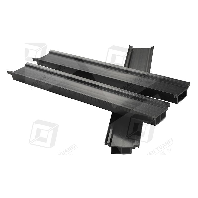
We must evaluate the structural differences between standard and advanced profile geometries. Manufacturers engineer multiple shapes to solve highly specific architectural challenges. Understanding these categories helps you specify the correct structural tie for your project.
The I-shape features a simple, flat structural tie between aluminum extrusions. Manufacturers use it frequently in entry-level commercial framing. It proves sufficient for basic thermal decoupling in mild climates. However, it offers limited mechanical resistance to lateral twisting. You will find it performs poorly at integrated water management. Basic applications accept them, but extreme weather exposures demand advanced solutions.
These profiles feature intentional curved or stepped designs. A C-shape increases the physical path heat must travel. This extended path improves overall thermal resistance naturally. It also adds deliberate structural elasticity to the assembly. This elasticity helps absorb building settlement forces safely. It prevents building shifts from fracturing the delicate internal seals over time.
These advanced profiles feature complex internal chambers. You will often see protruding fins or integrated flags extruded directly into the shape. They represent the premium standard for extreme weather applications. Engineered fins provide direct striking points for center gaskets. Hollow chambers act as functional internal baffles. They disrupt high wind pressure and block active water ingress effectively.
Profile Geometry Comparison Chart
Geometry Type | Structural Rigidity | Water Management | Ideal Application Environment |
|---|---|---|---|
Standard I-Shape | Low to Moderate | Poor | Basic decoupling, mild stable climates |
C-Shape (Omega) | Moderate (Elastic) | Fair | Mid-rise buildings prone to settlement |
Multi-Cavity / Finned | High | Excellent | High-rise, coastal, extreme weather zones |
We need to map specific geometric features to actual field outcomes. How do these shapes actively stop water and air penetration? The physical design of a polyamide thermal break dictates its weather resistance capabilities.
Look for sophisticated geometries featuring extruded polyamide fins. These fins align perfectly with primary EPDM central gaskets. They create a rigid, unyielding barrier against wind-driven rain. Standard aluminum channels cannot achieve this intersection without creating a thermal bridge. A dedicated fin ensures continuous, even compression across the entire gasket. You secure the weather seal permanently against dynamic weather events.
Multi-cavity profiles divide the gap between aluminum extrusions into distinct zones. They create dedicated internal pressure chambers. This specific geometry neutralizes external wind pressure drops. It stops pressure differentials from forcing water inward through tiny crevices. Instead, infiltrated water drains naturally by gravity. Dedicated internal chambers channel this water safely toward exterior weep holes.
Engineers must evaluate the moment of inertia within the selected geometry. A wider, reinforced hollow geometry offers superior shear strength. It prevents the interior and exterior aluminum halves from sliding independently. We call this independent movement shear slip. Stopping shear slip ensures constant, uniform pressure on all perimeter air seals. High shear strength guarantees long-term geometric stability under load.
The best conceptual geometry fails if manufacturers ignore assembly tolerances. Proper factory assembly strictly dictates final field performance. You must understand the risks involved during the fabrication phase.
The profile geometry must lock securely into the aluminum knurling. Factory rolling and crimping processes must apply perfectly even pressure. Uneven pressure during assembly warps the rigid strut. Warping creates microscopic gaps between the plastic and the metal. These microscopic gaps allow immediate, undetectable air infiltration. Precision during factory manufacturing remains absolutely non-negotiable for high-performance facades.
Glass-fiber-reinforced polyamide profiles expand and contract alongside aluminum frames. They share an identical thermal expansion rate. This exact synergy prevents stress fractures. It differs entirely from polyurethane pour-and-debridge systems. Manufacturers must avoid using inferior plastics in complex, multi-cavity geometries. Poor materials distort heavily during harsh summer-winter temperature swings. This distortion breaks the internal water seals completely.
Highly complex multi-cavity geometries require highly precise machining for weep holes. Over-engineered structural breaks carry unique implementation risks. They can inadvertently trap infiltrated water inside the frame. Flawed drainage routing logic causes internal backups rapidly. Manufacturers must design clear, unobstructed gravity pathways. Water must exit the aluminum frame quickly without pooling.
Common Mistake: Specifying multi-cavity profiles without reviewing the manufacturer's weep hole routing guide.
Best Practice: Request a physical factory sample to verify crimping alignment and drainage paths visually.
Procurement phases require strict, evidence-based evaluation logic. You must review complex manufacturer submittals carefully. Follow these specific steps to guarantee weather resistance in your building envelope.
Demand Proof of Structural Testing: Do not accept standalone U-value calculations. Request comprehensive physical test reports from certified laboratories. Ask for specific Design Wind Pressure (DP) structural tests. Require detailed Air Leakage and Water Penetration Resistance data. Ensure the submitted data matches your proposed geometry exactly.
Inspect the Gasket-to-Break Intersection: Request a detailed cross-sectional CAD drawing of the assembly. Verify the primary weather gasket placement meticulously. It must compress directly against a rigid structural element. Do not accept flexible or unsupported gaps in the critical center seal zone.
Verify Material Specifications: Ensure the architectural specification strictly calls for glass-fiber-reinforced polyamide (PA66 GF25). Other unreinforced materials lack the necessary structural rigidity. They cannot maintain geometric integrity under sustained dynamic wind loads. Accept no material substitutions during the submittal review phase.
Following this precise logic removes guesswork from the procurement process. It forces manufacturers to prove their system's mechanical capabilities upfront. You protect the building interior from costly, unforeseen weather infiltration events.
Thermal breaks function as structural load-bearing components first. They act as energy insulators second. Selecting fenestration systems based purely on thermal bridging metrics proves highly risky. It ignores the active mechanical realities of commercial building facades. Dynamic wind loads demand robust, engineered internal defenses. You must prioritize advanced, multi-cavity geometries for critical applications. These rigid designs offer the most reliable mechanism to ensure long-term air and water tightness. They effectively block capillary suction and neutralize wind pressure drops. Specify strong profile geometries alongside thermal metrics to guarantee ultimate facade resilience and interior comfort.
A: No. Thermal breaks are rolled and crimped into aluminum extrusions during the manufacturing process. Upgrading requires entirely new framing systems.
A: Not inherently. While wider breaks improve thermal performance, they can actually decrease structural rigidity if the geometry isn't reinforced (e.g., moving from a solid I-shape to a multi-cavity hollow shape). Rigidity, not just width, dictates seal performance.
A: Polyamide strips are extruded independently, allowing for highly complex, precise shapes (fins, hollows) before being joined to the aluminum. Polyurethane is poured as a liquid into a channel and cured, limiting it to simple, monolithic shapes that offer less targeted support for advanced gasket designs.


