

close
Choose Your Site
Global
Social Media

Author: Site Editor Publish Time: 2026-08-28 Origin: Site
Fenestration engineers and system designers face a continuous struggle. You must achieve stringent Uf-value targets without compromising structural integrity or manufacturing efficiency. The challenge lies in balancing strict thermal codes against real-world assembly constraints on the factory floor. While the base material, PA66 GF25, inherently provides low thermal conductivity, actual performance in modern aluminum windows heavily depends on cross-sectional geometry. Simply making the thermal break wider is no longer enough to meet modern demands. We built this technical evaluation framework to help buyers and specifiers assess different geometry types. You will learn how to properly evaluate these intricate shapes against thermal, acoustic, and assembly requirements. Read on to master the careful balance between complex extrusion design and practical application in commercial fenestration systems.
Profile geometry dictates the suppression of convective heat transfer; multi-cavity and finned shapes outperform standard solid struts.
Maximizing thermal insulation through complex geometries often introduces structural trade-offs that must be mitigated during the crimping process.
A well-specified geometry not only lowers U-values but acts as a highly effective soundproof polyamide 66 profile by disrupting acoustic bridging.
Procurement decisions should balance desired thermal performance with extrusion tolerances, shear strength requirements, and system assembly realities.
Defining a successful thermal break requires looking beyond basic material properties. A high-performing system must meet rigorous Passive House standards. It must actively prevent interior condensation during harsh winters. Furthermore, it must easily comply with tightening local building codes. Achieving these outcomes relies heavily on the design of the internal cavity between the aluminum extrusions.
Heat travels through an aluminum-polyamide-aluminum assembly in three distinct ways. Conduction moves heat directly through the solid materials. Convection transfers heat via air movement within the empty spaces. Radiation pushes heat across the gaps as electromagnetic waves. The polyamide material naturally resists conduction. However, empty spaces within the aluminum frame create an environment where convection and radiation thrive.
This is exactly why geometry matters. Modifying the shape specifically disrupts convective air loops inside the cavity. When you place a barrier inside an open space, air can no longer circulate freely. This physical disruption provides massive thermal returns. Linear thickness increases simply cannot achieve these results alone. You must sculpt the space to stop air movement and reflect radiant heat.
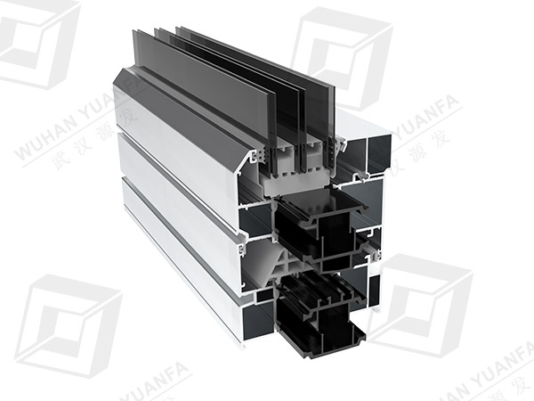
Understanding the available shapes helps you select the right component for your specific fenestration project. Different geometries serve entirely different market segments.
These represent the most fundamental approach to thermal breaking. They are simple, highly cost-effective, and provide excellent baseline shear strength. Extrusion processes for these shapes remain highly stable. They serve standard commercial applications perfectly. When baseline thermal breaks are sufficient for the local climate, a standard Polyamide Profile in an I-shape delivers reliable, predictable performance without inflating project budgets.
The C-shape, or Omega profile, introduces a clever structural trick. It extends the heat conduction path without increasing the overall width. By curving the material, heat must travel a longer physical distance to cross the gap. These shapes excel in systems requiring moderate thermal upgrades. They work exceptionally well within constrained spatial footprints where wider aluminum frames are simply impossible to use.
Multi-chamber geometries take thermal performance to the next level. They trap air in isolated pockets. This effectively eliminates large-scale convective heat transfer. Stagnant air acts as a fantastic insulator. You will typically specify these shapes for high-performance and extreme-climate fenestration. They demand tighter manufacturing tolerances but deliver exceptional Uf-value reductions.
These represent the pinnacle of thermal break design. They feature protruding flags or fins extending from the main body. These fins interface directly with central gaskets. This connection creates continuous isonodes, or isothermal lines, across the entire window system. Premium systems targeting the lowest possible Uf-values rely heavily on these tailored, complex geometries.
Geometry Comparison Chart
Geometry Type | Primary Mechanism | Manufacturing Complexity | Ideal Use Case |
|---|---|---|---|
Solid / I-Shape | Basic conduction block | Low | Standard commercial, mild climates |
C-Shape / Omega | Extended conduction path | Medium | Space-constrained thermal upgrades |
Hollow / Multi-Chamber | Convection suppression | High | Extreme climates, high-performance |
Finned / Tail | Continuous isonodes creation | Very High | Passive House, premium residential |
Upgrading profile shapes requires careful analysis. You must balance thermal goals against mechanical realities. Every geometric modification introduces a new set of evaluation dimensions linking features directly to outcomes.
Larger, more complex hollow shapes often exhibit different tensile strengths. Transverse stability can vary significantly compared to solid struts. Complex web designs thin out the material in certain areas. It remains absolutely vital to retain at least 25% glass fiber reinforcement (PA66 GF25) uniformly across these complex shapes. Uneven fiber distribution leads to weak points. These weak points can cause catastrophic structural failure under heavy wind loads or building movement.
Thermal breaks do more than just block heat. They also stop noise. Multi-chamber geometries inherently disrupt sound wave transmission. They utilize the mass-spring-mass principle effectively. The alternating layers of polyamide and trapped air force sound waves to expend energy. A properly designed multi-cavity structure functions as a highly reliable Soundproof Polyamide 66 Profile. You will find them ideal for urban environments, airport hotels, or any high-noise location requiring strict acoustic decoupling.
Engineers must remain cautious of diminishing returns. Adding countless internal chambers eventually hurts performance. If the internal wall thickness becomes too thin, the profile loses essential rigidity. You risk severe profile failure under wind loads. Furthermore, ultra-thin walls cannot hold their shape during the knurling and crimping process. Always verify structural simulations before committing to an overly complex cavity design.
Theoretical designs often clash with factory floor realities. Switching to complex profile geometries changes the entire assembly dynamic. Production managers must adapt their processes to handle delicate, highly engineered components.
Hollow or highly detailed profiles require precise mechanical handling. Standard I-shapes tolerate aggressive crimping. Complex shapes do not. They require precise knurling wheel alignment and perfectly calibrated rolling pressure. Excessive force will crush the hollow polyamide chambers. Insufficient force will fail to secure the aluminum, destroying the required shear capacity. You must recalibrate machinery specifically for each new geometry.
The bi-metallic effect poses a significant risk to complex assemblies. Aluminum and polyamide expand at entirely different rates under extreme sun exposure. A dark-colored aluminum frame heats up rapidly, expanding outward. The inner polyamide layer remains cooler and expands less. Complex geometries must accommodate this differential expansion without bowing or shearing. Specialized sliding geometries or flexible fin designs often mitigate this specific risk.
Sourcing cheap, complex profiles invites disaster. Poor extrusion tolerances in multi-cavity shapes create cascading failures. If the geometry deviates by even fractions of a millimeter, standard central gaskets will not seat properly. This failure immediately leads to water ingress, drafts, and compromised acoustic performance.
Factory Floor Best Practices:
Calibrate rolling machines daily to match specific cavity wall thicknesses.
Inspect knurling depth continuously to ensure proper shear strength grip.
Conduct weekly pull-tests on complex profile assemblies.
Store profiles in climate-controlled areas to prevent moisture absorption before crimping.
Choosing the correct shape requires a methodical approach. You must match the geometry to the exact product tier. Over-engineering a standard commercial window wastes money. Under-engineering a premium residential door ruins the brand reputation.
Begin by defining your target Uf-value and structural load requirements. For standard commercial tiers, prioritize shear strength and fast assembly using I-shapes or Omega shapes. For premium residential tiers, prioritize thermal and acoustic performance using multi-chamber or finned designs.
Never accept vendor claims without documented proof. Advise your procurement teams to request specific data. Demand shear strength test results based on the EN 14024 standard. Require thermal calculation reports based on the EN ISO 10077-2 standard. These universally accepted frameworks guarantee baseline performance and structural safety.
Simulation Capabilities: Look for suppliers offering robust thermal simulation support. They should use flixo or THERM modeling.
Proactive Proof: The supplier must prove the U-value impact of the geometry before you invest in tooling and extrusion.
Material Transparency: Demand certificates proving uniform PA66 GF25 distribution.
Tolerance Guarantees: Ensure they outline strict dimensional tolerance limits in their supply contracts.
We highly recommend initiating a pilot assembly test. Order a small batch of the proposed geometry. Run it through your factory's crimping lines. This physical test verifies both the thermal simulation results and the mechanical crimping viability. It reveals hidden assembly issues before full-scale production begins.
The optimal shape is rarely the one boasting the lowest theoretical U-value. True success comes from finding the geometry that perfectly aligns with your specific constraints. You must balance the manufacturer's assembly capabilities against strict structural requirements and aggressive acoustic targets. Overly complex designs often fail on the factory floor if machinery cannot handle delicate hollow chambers.
Procurement and engineering teams must work together to evaluate these trade-offs early in the design phase. Rely on proven EN standards and insist on transparent testing protocols. We encourage fenestration engineers to request comprehensive geometric thermal simulations and detailed material specification sheets from trusted extrusion partners today. A well-chosen profile secures your system's long-term performance and market competitiveness.
A: Switching geometries typically reduces the Uf-value by 15% to 30%. However, this exact percentage depends heavily on the overall system depth and the number of isolated air chambers introduced. Deeper systems see more dramatic improvements.
A: It can, but proper engineering prevents this. Maintaining adequate wall thickness and ensuring a uniform 25% glass fiber (PA66 GF25) distribution prevents structural degradation. Precise crimping calibration also ensures high shear capacity.
A: Yes. Acoustic decoupling is achieved through multiple air chambers and varying wall masses. These structures disrupt sound wave transmission using the mass-spring-mass principle, significantly lowering noise penetration in high-rise or urban buildings.
A: Standard off-the-shelf geometries carry zero tooling costs. Custom multi-chamber or finned designs require B2B tooling investments, generally ranging from $1,000 to $3,000 per die, depending on internal complexity and tolerance requirements.


